How to Specify Linear Motion Guides

Linear motion guides are essential in many industries, facilitating the movement and positioning of tools, workpieces, parts, assemblies, and even complete machine systems. These guides can range from just a few centimeters to several meters in length, operate at speeds over 5 meters per second, and achieve positioning accuracy better than 1 micron.
However, choosing the right linear guide rail for a specific application can be complex due to the variety of manufacturers, construction methods, materials, and specifications.
Basic Construction of Linear Motion Guides
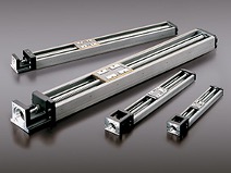
Linear motion guides typically consist of a profile rail over which a block or carriage runs. This setup is designed to carry a workpiece or tool, supported by rolling bearing elements that ensure smooth operation with high precision and repeatability. The use of rolling element mechanisms dates back thousands of years, with notable examples such as the builders of Stonehenge and the Pyramids moving large stone blocks on timber rollers.
Modern linear guides, however, trace their development to 1944 with the introduction of a round shaft linear guide rail system in the USA.
This basic design has evolved into the profile rail linear guideway (linear rail system) introduced in 1973, which features two-point circular arc contact and forms the basis of today’s foremost linear guides. A modern linear guide consists of a rail, carriage, balls, end caps, ball retainers, and associated seals, as well as lubrication and mounting mechanisms.
Operation and Design Considerations
The operation of a linear motion system is relatively simple, with the linear rail guide and carriage separated by a caged series of steel balls. These balls, mounted within raceways, enable smooth movement along the rail, with return mechanisms in each end plate recirculating the balls as the carriage moves. Raceways are typically shaped using either gothic arch or circular arc structures.
- Gothic Arch Raceways: These provide higher rigidity with four contact points per ball but suffer from higher differential slip under heavy loads, leading to increased friction, noise, and heat. They are generally used for miniature linear guides where loads and frictional forces are lower.
- Circular Arc Raceways: Preferable for most applications, especially when configured with four raceways per carriage. This setup offers greater load-carrying capacity, self-adjusting properties, and higher stiffness and reliability.
Ball Mechanism Design
Efficient operation of linear motion control products depends significantly on the design and construction of the ball mechanisms. Traditionally, balls were arranged in a continuous loop through the raceway without cage retention, relying on lubricating grease to minimize friction. However, this setup still resulted in high friction levels between balls and raceway walls, increasing noise, heat, and reducing smoothness, repeatability, and operating life.
Modern linear Caged Ball guides address these issues by incorporating mechanisms that seal each row of precision-ground steel balls in a cage, each locked in with an independent pocket of grease. This design almost eliminates maintenance, minimizes friction, and allows for smooth, quiet, high-speed operation with positional accuracy better than 1 micron. Additionally, these guides are highly reliable and can travel over 40,000 km without maintenance or relubrication.
How to Specify Linear Motion Guides – Part II
In today's industrial marketplace, there is a plethora of linear motion control systems available from many different manufacturers and suppliers. To the uninitiated, many of these linear motion control products and linear guide systems can seem similar in terms of performance and functionality, making it difficult to select an appropriate solution on any basis other than cost or possibly a headline performance figure.
In practice, however, cost should be only one of a number of factors on which a purchasing decision should be based, and it is therefore important both to understand the key specifications quoted by suppliers and to appreciate the fact that the same specification can be interpreted or quoted differently by different suppliers. A comprehensive linear motion design guide can be instrumental in navigating these complexities.
In addition, although some of the information contained within linear motion product catalogs is generally detailed and accurate, there are often terms or definitions required for accurate product specification that are not always clear. This article seeks to provide a brief guide to the common terms and what they mean.
Dynamic load ratings illustrate the capacity of the product and ultimately help to determine the service life of a linear motion system when a specific dynamic load is applied from above (radial), below (reverse radial), or from the side (lateral).
Linear motion guides can be divided into two categories: four-way equal type and radial type. The former is capable of handling loads from all directions and has a dynamic load rating that is standard or consistent regardless of the direction of the applied force, while the latter type of guides are specifically designed to handle radial loads and will have a different dynamic rating for top/bottom and side loads. Product selection can therefore be optimized against the load direction to give the best level of overall performance.
The load factor (fw) indicates the relationship between the load-carrying capacity of a LM guide and an external force generated by vibration or an unexpected impact. In a demanding factory or processing application, this figure can be used to modify the ability of a linear guide system to respond under particularly harsh operating conditions, where environmental factors can have a negative effect on a nominal fatigue life calculation.
It should be noted that selecting a linear guide that can bear the maximum possible load, both when it is stationary and in motion, is vital to ensure consistent and accurate movement. It is normal therefore to consider the static safety value (Fs) to safeguard against shock loading, as well as determining fatigue life expectancy under dynamic conditions.
Radial clearance data can be used as a guide to help maximize the precision, performance, and installed rigidity of linear motion products. The term covers both normal and negative clearance. The first applies where the loading direction is fixed and where impact and vibration are slight and the axes installed in parallel, while negative clearance relates to more specific applications, such as high precision or heavy loads.
Negative clearance is determined by the internal load, or preload, exerted on the rolling linear motion components, to increase block rigidity and reduce clearances and is often subdivided into clearance (C1) for a light preload or clearance (C0) for a moderate preload.
There are also several application-related criteria that can influence the overall performance of a linear motion system. These include linear guide rail and carriage spacing, the number of carriages within the system, the level of exposure to high acceleration and deceleration forces when loaded, the use of bump stops, system cleanliness, and the correct use of lubrication.
In effect, fatigue life is determined by all of the factors described above, being the total operating distance that a linear motion control product travels before its internal mechanisms start to deteriorate or surfaces start to wear or flake. In theory, similar products built to identical specifications should have similar service lives making a comparison relatively straightforward; in practice, however, this is rarely the case as differences in production techniques, choice of materials, and finishing processes will all affect long-term reliability.
Perhaps the simplest guideline for determining fatigue life is the general figure quoted by manufacturers for nominal life; this is generally taken from standard test data showing the total running distance that 90% of a sample series of identical linear motion systems have achieved without deterioration, under the same load conditions. Naturally, if higher levels of reliability are required, these can be built into the selection process, often by correct selection of product rather than simply increasing the size and capacity.
The data and information presented to customers by manufacturers of linear motion technology can often be complex, diverse, and sometimes conflicting. Gaining an understanding of the basic terms used in this industry will help design and mechanical engineers develop more efficient and reliable machinery.
Conclusion
Modern linear guide systems are versatile, high-precision devices used in various applications, including electronic pick-and-place, semiconductor manufacturing, medical equipment, machine tools, heavy-duty palletizing, and civil engineering for earthquake protection. Understanding how linear guide rail systems work and specifying them correctly is crucial for effective use.
For any questions or inquiries about THK products, please contact us at sales@technico.com or fill out our contact form at Technico Contact Us. Our team is ready to assist you with your specific requirements.